Forced Convection Heat Sink Calculator
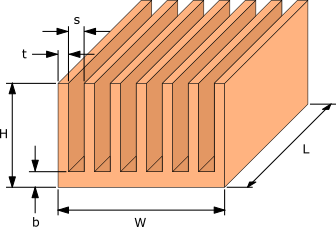
Calculates the width and number of fins of a fan cooled plate fin heat sink needed to keep a heat source below a maximum temperature. The fin spacing is set to the optimum for the fan, and fins are added until the temperature limit is met.
The heat sink is assumed to be ducted, so all of the fan's airflow passes between the fins, and the fan curve is treated as a straight line between its maximum flow rate and maximum pressure. The heat source is assumed to cover the whole base and be in perfect contact with it. The flow between the fins is laminar and steady, radiation is ignored, and air properties are taken at the ambient temperature at sea level. The method is described in Heat sink design optimization for forced convection.
Results
- Heat source temperature
- -
- Thermal resistance
- -
- Optimum fin spacing, s
- -
- Airflow through heat sink
- -
- Pressure drop
- -
- Air velocity between fins
- -
- Reynolds number
- -
Limits of this estimate
Three simplifications in this calculator may make a real design run hotter:
- The heat source is assumed to cover the whole base. Smaller components run hotter because the heat has to spread through the base.
- The fan curve is treated as a straight line. Most real fan curves are not.
- The flow is assumed to be ducted, so all of the fan's airflow passes between the fins. In a real design, some air may bypass the heat sink.
The full HeatSinkCalculator accounts for all three, handles multiple heat sources, and can optimize every dimension for temperature, weight or pressure drop.
Try the full calculatorNeed more than a first estimate?
The full HeatSinkCalculator uses your real fan curve, models impinging, ducted and bypass flow, handles real component sizes and multiple heat sources, and covers liquid cooling. It can also find the lightest heat sink, or the lowest pressure drop, that keeps your components below their temperature limit.


